
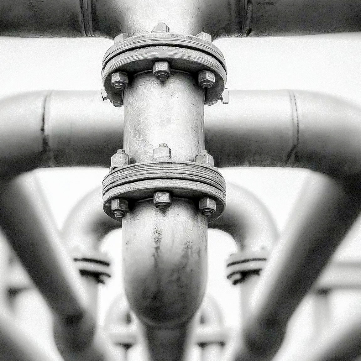
Pipe Fittings for Piping Systems, Pressure Vessels, and Process Piping
Fittings are the connectors that join pipe sections, change direction, alter diameter, and branch flow in piping systems across the oil and gas industry. From high-pressure wellhead piping to refinery process lines, the integrity of every piping system depends on correctly specified, fully traceable fittings.
HSP supplies a complete range of buttweld, socket weld, threaded, and flanged fittings manufactured to ASME, ASTM, ISO, NACE, and project-specific standards. Every fitting comes with full Mill Test Reports (MTRs), material certification, and NDE records as required.
Our Fittings Categories at a Glance
| Category | Primary Function | Key Standards |
|---|---|---|
| Buttweld Fittings | Welded connections for high-integrity, high-pressure piping | ASME B16.9, B16.28, MSS SP-43, MSS SP-75 |
| Socket Weld & Threaded Fittings | Small-bore piping connections | ASME B16.11, BS 3799 |
| Flanges | Pipe-to-pipe and pipe-to-equipment bolted connections | ASME B16.5, B16.47, B16.36, API 6A |
| Olets & Branch Connections | Branch connections from run pipe without tee fitting | MSS SP-97, MSS SP-105 |
| Swage Nipples & Bull Plugs | Pipe diameter transitions and end closures | MSS SP-95, ASME B16.11 |
| Gaskets | Flange joint sealing | ASME B16.20, B16.21 |
| Stud Bolts & Fasteners | Flange and equipment bolting | ASTM A193, A194, A320 |
| Piping Specialties | Strainers, steam traps, expansion joints, flame arrestors | ASME B16.34, API standards |
SUBCATEGORIES
BUTTWELD FITTINGS
Buttweld Fittings
High-Integrity Welded Connections for Critical Piping Systems
Buttweld fittings are joined to pipe by circumferential butt welding. They provide the highest integrity connection and are specified for all critical, high-pressure, high-temperature, and hazardous service piping in oil and gas facilities. They are the standard for ASME B31.3 process piping, B31.4 liquid pipelines, and B31.8 gas pipelines.
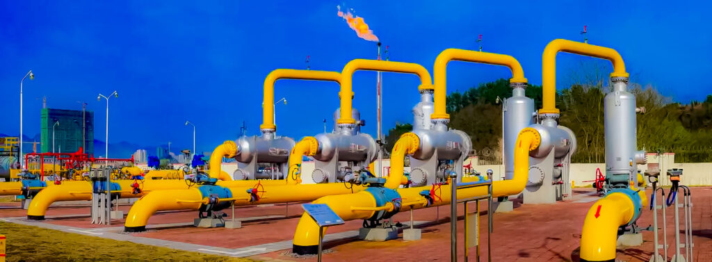
Available Fitting Types
| Fitting Type | Symbol | Function |
|---|---|---|
| 90° Long Radius Elbow (LR) | 90° LR ELL | Changes direction by 90°. Radius = 1.5 × nominal pipe size |
| 90° Short Radius Elbow (SR) | 90° SR ELL | Changes direction by 90°. Radius = 1.0 × nominal pipe size |
| 45° Elbow | 45° ELL | Changes direction by 45° |
| 180° Return Bend (Long Radius) | 180° LR | Changes direction by 180°. For heat exchangers and coils |
| 180° Return Bend (Short Radius) | 180° SR | Compact U-bend. Back-to-back for tube bundles |
| Straight Tee (Equal Tee) | TEE | Branches flow at 90°. All three ends same size |
| Reducing Tee | RED TEE | Branches flow at 90°. Branch smaller than run |
| Concentric Reducer | CONC RED | Gradual diameter reduction. Centerlines aligned. For horizontal lines |
| Eccentric Reducer | ECC RED | Gradual diameter reduction. Flat side top or bottom. For pump suction and pipe racks |
| Cap (End Cap) | CAP | Closes pipe end. Ellipsoidal, hemispherical, or dished |
| Stub End (Lap Joint Stub End) | STUB END | Used with lap joint flange. Allows flange rotation for bolt-hole alignment |
| Cross (Equal) | CROSS | Four-way branch connection |
| Reducing Cross | RED CROSS | Four-way branch with reduced branches |
Applicable Standards
| Standard | Scope |
|---|---|
| ASME B16.9 | Factory-made wrought buttweld fittings (1/2″ to 48″) |
| ASME B16.28 | Short radius elbows and returns |
| MSS SP-43 | Lightweight corrosion-resistant buttweld fittings (stainless) |
| MSS SP-75 | High-test buttweld fittings for pipeline service (up to 60″, higher yield strength) |
| ASME B16.49 | Induction bends for transportation and distribution piping |
| NACE MR0175 / ISO 15156 | Sour service material requirements |
Size & Wall Thickness
| Parameter | Range |
|---|---|
| Sizes | 1/2″ (DN15) to 60″ (DN1500) |
| Wall Thickness | SCH 5S, 10S, 10, 20, 30, 40S, 40, STD, 60, 80S, 80, XS, 100, 120, 140, 160, XXS |
| End Preparation | Beveled per ASME B16.25 |
Material Options
| Material | ASTM Spec (Pipe) | ASTM Spec (Fitting) | Typical Service |
|---|---|---|---|
| Carbon Steel | A106 Gr.B | A234 WPB | General process, sweet hydrocarbon |
| Carbon Steel (Low Temp) | A333 Gr.6 | A420 WPL6 | Cryogenic, LPG, LNG |
| Carbon Steel (High Temp) | A335 P11/P22 | A234 WP11/WP22 | High temperature, steam |
| Stainless 304/304L | A312 TP304/304L | A403 WP304/304L | Corrosive, food-grade |
| Stainless 316/316L | A312 TP316/316L | A403 WP316/316L | Chlorides, offshore, sour |
| Duplex (UNS S31803/S32205) | A790 | A815 UNS S31803 | High chlorides, seawater |
| Super Duplex (UNS S32750) | A790 | A815 UNS S32750 | Extreme chlorides, subsea |
| Inconel 625 | B444 Gr.1 | B366 WPNICMC | Sour HPHT, extreme corrosion |
Optional Testing & Inspection
- PMI (Positive Material Identification): Verifies alloy composition on finished fitting
- Radiographic Testing (RT): Volumetric inspection of weld area (for welded fittings)
- Magnetic Particle / Dye Penetrant (MPI/DPI): Surface crack detection
- Intergranular Corrosion Test (IGC): Per ASTM A262 for stainless fittings
- Impact Testing: Charpy V-notch at specified temperature
- Hardness Testing: For sour service (NACE MR0175 compliance)
SOCKET WELD & THREADED FITTINGS
Socket Weld & Threaded Fittings
Small-Bore Fittings for Utility, Instrument, and Secondary Process Piping
Socket weld and threaded fittings are used for small-bore piping (typically ≤ 2″ or DN50). They provide a compact, cost-effective alternative to buttweld fittings for non-critical or lower-pressure service. Socket weld fittings are joined by fillet weld; threaded fittings are screwed onto threaded pipe ends.
Applicable Standards
| Standard | Scope |
|---|---|
| ASME B16.11 | Forged fittings, socket-welding and threaded |
| BS 3799 | British standard for forged steel screwed and socket-welding fittings |
| MSS SP-83 | Socket weld and threaded unions |
| MSS SP-79 | Socket weld reducer inserts |
Socket Weld Fittings
| Fitting Type | Function |
|---|---|
| 90° Elbow | Direction change |
| 45° Elbow | Direction change |
| Tee (Equal & Reducing) | Branch connection |
| Cross | Four-way branch |
| Coupling (Full & Half) | Joins two pipes same diameter |
| Reducing Coupling | Joins two pipes different diameter |
| Cap | Closes pipe end |
| Union | Demountable connection for maintenance |
Key Feature: Socket weld fittings have a recessed socket that the pipe slides into. A gap (typically 1.6mm) is left between pipe end and socket bottom before welding to accommodate thermal expansion.
Pressure Classes: 3000#, 6000#, 9000#
Threaded Fittings
| Fitting Type | Function |
|---|---|
| 90° Elbow | Direction change |
| 45° Elbow | Direction change |
| Tee | Branch connection |
| Coupling | Joins two pipes |
| Cap | Closes pipe end |
| Hex Nipple | Short connector, hex center for wrench |
| Swage Nipple / Reducing Nipple | Diameter transition |
| Plug (Hex Head, Square Head, Round Head) | Closes fitting or valve opening |
| Bushing | Reduces fitting opening size |
| Union | Demountable connection |
Thread Types: NPT (National Pipe Taper) per ASME B1.20.1 is standard for oil and gas.
Pressure Classes: 2000#, 3000#, 6000#
Material Options
| Material | ASTM Spec (Forged) | Application |
|---|---|---|
| Carbon Steel | A105 | General sweet service |
| Carbon Steel (Low Temp) | A350 LF2 | Cryogenic, low temperature |
| Carbon Steel (Sour) | A105 (NACE MR0175) | Sour service with hardness control |
| Stainless 304/304L | A182 F304/F304L | General corrosion |
| Stainless 316/316L | A182 F316/F316L | Chlorides, offshore, sour |
| Duplex | A182 F51 / F53 | High chlorides |
| Inconel 625 | B564 N06625 | Sour HPHT, extreme corrosion |
FLANGES
Flanges
Bolted Connections for Piping, Valves, and Equipment
Flanges provide demountable connections between pipe sections, valves, pumps, vessels, and other equipment. They are the second most common connection type after buttwelds and are essential wherever maintenance, inspection, or future modification access is required.
Flange Types (ASME B16.5 / B16.47)
| Flange Type | Description | Typical Application |
|---|---|---|
| Weld Neck (WN) | Long tapered hub butt-welded to pipe. Transfers stress smoothly | High pressure, high temperature, cyclic service, hazardous fluids |
| Slip-On (SO) | Pipe slips inside flange bore. Two fillet welds (inside and outside) | Lower pressure, non-critical service. Lower cost |
| Socket Weld (SW) | Pipe inserts into socket. One fillet weld | Small bore (≤2″), high pressure |
| Blind (BL) | Solid disc. Closes off a flanged opening | End of pipe run, vessel manway, future connection |
| Lap Joint (LJ) | Used with stub end. No direct weld to pipe | Systems requiring frequent disassembly, costly alloys (flange can be carbon steel with stainless stub end) |
| Threaded (TH) | Screwed onto threaded pipe. No welding | Low pressure, small bore, hazardous areas (no hot work) |
| Orifice (Orifice Flange) | Weld neck or slip-on with pressure tap holes | Metering runs for orifice plates |
| Spectacle Blind / Spade & Spacer | Installed between two flanges. Solid (spade) or open (spacer) | Positive isolation during maintenance |
| Long Weld Neck (LWN) | Extended straight hub | Pressure vessels, columns, nozzle connections |
| Reducing Flange | WN or SO with smaller bore than flange size | Connecting different pipe sizes at flange joint |
| Expander Flange | WN with expanding bore from smaller pipe to larger flange | Reducing number of reducers in the system |
Flange Facing Types
| Facing | Description | Application |
|---|---|---|
| Raised Face (RF) | Serrated raised surface. 1.6mm (1/16″) for ≤600#, 6.4mm (1/4″) for ≥900# | Standard for ASME flanges. Most common in process plants |
| Flat Face (FF) | Full flat face | Cast iron flanges, FRP, low pressure |
| Ring Type Joint (RTJ) | Precision machined groove accepts metal ring gasket | High pressure, high temperature, critical service, API 6A wellheads |
| Male & Female (M&F) | One flange has raised male face, other has matching female recess | Low pressure, small sizes (less common now) |
| Tongue & Groove (T&G) | One flange has raised ring, other has matching groove | Self-aligning, for toxic or expensive fluids |
Applicable Standards
| Standard | Scope | Size Range | Pressure Range |
|---|---|---|---|
| ASME B16.5 | Pipe flanges and flanged fittings | 1/2″ to 24″ | 150# to 2500# |
| ASME B16.47 Series A (MSS SP-44) | Large diameter flanges | 26″ to 60″ | 150# to 900# |
| ASME B16.47 Series B (API 605) | Large diameter flanges | 26″ to 60″ | 150# to 900# |
| ASME B16.36 | Orifice flanges | 1″ to 24″ | 300# to 2500# |
| API 6A | Wellhead and Christmas tree flanges | 1-13/16″ to 30″ | 2,000 to 20,000 psi |
| API 6B | API flanges (superseded by API 6A) | Various | Up to 5,000 psi |
| AWWA C207 | Waterworks flanges | 4″ to 144″ | Class B to Class F |
| MSS SP-44 | Steel pipeline flanges | 12″ to 60″ | 150# to 900# |
Flange Material Options
| Material | ASTM Forging Spec | Service |
|---|---|---|
| Carbon Steel | A105 | General sweet service |
| Carbon Steel (Service) | A105N | Normalized for better toughness |
| Carbon Steel (Low Temp) | A350 LF2 | -46°C applications |
| Carbon Steel (Sour) | A105/A350 (NACE MR0175) | H2S service with hardness control |
| Chrome-Moly (1.25Cr-0.5Mo) | A182 F11 | High temperature |
| Chrome-Moly (2.25Cr-1Mo) | A182 F22 | Higher temperature |
| Stainless 304/304L | A182 F304/F304L | General corrosive |
| Stainless 316/316L | A182 F316/F316L | Chlorides, offshore, sour |
| Stainless 321 | A182 F321 | High temperature (stabilized) |
| Stainless 347 | A182 F347 | High temperature (stabilized) |
| Duplex (2205) | A182 F51 (UNS S31803) | High chlorides |
| Super Duplex (2507) | A182 F53 (UNS S32750) | Extreme chlorides, subsea |
| Inconel 625 | B564 N06625 | Sour HPHT |
| Inconel 825 | B564 N08825 | Sour, acid |
OLETS & BRANCH CONNECTIONS
Olets & Branch Connections
Integrally Reinforced Branch Outlet Fittings
Olets (a Bonney Forge-originated term, now used generically for branch outlet fittings) provide a branch connection from a run pipe without cutting the pipe and welding in a tee. They are butt-welded or socket-welded to the run pipe, providing a reinforced opening that compensates for the material removed.
Types of Branch Connection Fittings
| Type | Standard | Description | Application |
|---|---|---|---|
| Weldolets | MSS SP-97 | Buttweld branch outlet. Integral reinforcement. Full penetration weld | Most common. High pressure, critical service |
| Sockolets | MSS SP-97 | Socket weld branch outlet | Small-bore instrument and drain connections |
| Thredolets | MSS SP-97 | Threaded branch outlet | Small-bore threaded instrument connections |
| Sweepolets | MSS SP-97 | Long-radius contoured branch. Reduces stress and erosion | High-velocity, erosive, and cyclic service |
| Elbolets | MSS SP-97 | Branch outlet on elbow rather than straight pipe | Space-constrained piping, vessel connections |
| Latrolets | MSS SP-97 | Branch outlet at 45° angle from run pipe | Directional connections, instrumentation |
| Nipolets | MSS SP-97 | Outlet with integral nipple (male threaded or socket end) | Valves, instruments, vents, drains |
| Flangolets | MSS SP-97 | Branch outlet with integral flange face | Flanged instrument, valve, or drain connection |
| Couplets | MSS SP-105 | Full-encirclement reinforcement saddle + branch outlet | Thin-wall pipe where single-sided reinforcement insufficient |
Size Range: 1/4″ to 24″ branch size on 2″ to 60″ run pipe
Facing: Buttweld, socket weld, threaded, or flanged per requirement
Materials: As per flange and buttweld fitting material specifications (A105, A182, A350 LF2, stainless, duplex, etc.)
SWAGE NIPPLES, BULL PLUGS & END CLOSURES
Swage Nipples, Bull Plugs & End Closures
Pipe Diameter Transitions and Permanent End Closures
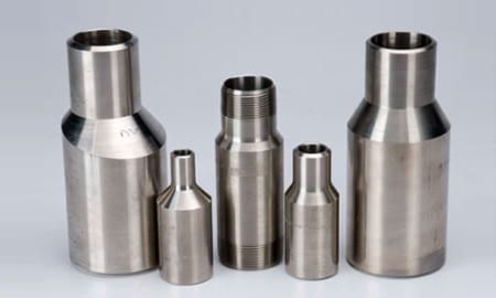
Swage Nipples
Swage nipples are short pipe sections used to transition between two different pipe diameters. They are a compact alternative to using a reducer plus two couplings.
| Type | Description | Application |
|---|---|---|
| Concentric Swage | Both ends share same centerline | Vertical piping, in-line transitions |
| Eccentric Swage | One side flat, other tapered | Pump suction, pipe rack piping (drainage) |
End Types: Plain Both Ends (PBE), Threaded Both Ends (TBE), Beveled Both Ends (BLE), Plain Large End / Threaded Small End (PLE/TSE), Threaded Large End / Plain Small End (TLE/PSE)
Standard: MSS SP-95
Sizes: 1/4″ to 12″ (larger sizes typically use buttweld reducers)
Bull Plugs
Solid plugs with male NPT thread. Used to permanently or semi-permanently close threaded openings in piping, fittings, and pressure vessels.
- Standard: ASME B16.11
- Head Types: Hex head (wrench-tightened), square head (wrench), round head (low profile)
- Sizes: 1/8″ to 4″ NPT
- Materials: A105, A182, A350 LF2, stainless
NPT Plugs
Similar to bull plugs but smaller. Used for instrument tap holes, vent and drain ports, and pipe plugs on threaded fittings.
| Type | Description |
|---|---|
| Hex Head Plug | Standard. Wrench-tightened |
| Square Head Plug | Higher torque capacity |
| Socket Head Plug (Allen Plug) | Countersunk. Low profile, no external hex |
| Round Head Plug | Smooth external profile |
Pipe Caps
Welded or threaded closures for pipe ends.
- Buttweld Cap: Per ASME B16.9. Ellipsoidal, hemispherical, or dished
- Threaded Cap: Per ASME B16.11. For threaded pipe ends
- Socket Weld Cap: Per ASME B16.11. For socket weld pipe ends
GASKETS
Gaskets
Sealing Elements for Flanged Joints
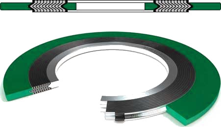
Gaskets are the critical sealing component in every bolted flange connection. A correctly specified gasket prevents leakage across the full range of operating pressure, temperature, and chemical conditions while accommodating flange surface imperfections and thermal cycling.
Gasket Types for ASME Flanges
| Type | Standard | Construction | Best For |
|---|---|---|---|
| Spiral Wound | ASME B16.20 | Alternating V-shaped metal winding + soft filler. Outer guide ring + inner ring | The workhorse gasket. All process services, wide P/T range |
| Ring Type Joint (RTJ) | ASME B16.20, API 6A | Solid metal ring. Octagonal (R-type) or oval | High pressure, high temperature, critical service, wellheads |
| Kammprofile / Grooved Metal | ASME B16.20 | Serrated metal core with soft facing layer on both sides | Heat exchangers, large vessels, where spiral wound not suitable |
| Jacketed | ASME B16.20 | Soft filler fully or partially enclosed in metal jacket | Heat exchangers, wide temperature range |
| Corrugated Metal (CMG) | — | Corrugated metal ring with soft facing | Low seating stress applications |
| Non-Metallic (Cut / Sheet) | ASME B16.21 | Compressed fiber, PTFE, flexible graphite without metal reinforcement | Low pressure, non-critical, large diameters |
| Double-Jacketed | ASME B16.20 | Soft filler completely enclosed in two-piece metal jacket | Heat exchangers, pumps, valves |
| PTFE Envelope | — | PTFE envelope around elastomer or fiber core | Strong chemicals, where metal contamination prohibited |
| Insulation Gasket | — | Gasket with isolation sleeve and washer | Electrical isolation of flanges (CP systems) |
Spiral Wound Gasket Components
| Component | Material Options | Function |
|---|---|---|
| Metal Winding | 304, 316L, 321, 347, Duplex, Inconel 600/625, Monel 400, Titanium | Provides structural strength and resilience |
| Filler Material | Flexible Graphite, PTFE, Mica, Phlogopite | Provides sealability. Graphite for high temp, PTFE for chemical |
| Outer Guide Ring | Carbon Steel (painted), 304 SS, 316 SS | Centering. Prevents over-compression |
| Inner Ring | 304 SS, 316 SS, Duplex, Inconel | Prevents filler erosion, protects against corrosion, heat shield |
Spiral Wound Color Coding (Per ASME B16.20):
- Outer ring color identifies metal winding material
- Filler stripe color identifies filler type
RTJ Gasket Types
| Type | Standard | Cross-Section | Application |
|---|---|---|---|
| Type R Oval | ASME B16.20 | Oval | Standard ASME RTJ flanges. Original design. Reusable limited times |
| Type R Octagonal | ASME B16.20 | Octagonal | Modern standard. Better sealing. Not reusable after compression |
| Type RX | API 6A | Pressure-energized octagonal | API 6B flanges, wellheads, some ASME sizes |
| Type BX | API 6A | Octagonal with beveled corners | API 6BX flanges, high-pressure wellheads, subsea |
RTJ Material & Hardness:
| Material | Maximum Hardness (HRB) | Application |
|---|---|---|
| Soft Iron | 56 | General sweet service. Softer than flange groove |
| Low Carbon Steel | 68 | General service |
| 4-6% Chrome / 1/2% Moly | 86 | Moderate temperature |
| 304 SS | 83 | Corrosive, moderate temp |
| 316 SS | 83 | Corrosive, chlorides, sour |
| 347 SS | 83 | High temperature (stabilized) |
| Inconel 825 | 92 | Sour, acid, high chloride |
| Inconel 625 | 99 | Sour HPHT, extreme corrosion |
STUD BOLTS & FASTENERS
Stud Bolts & Fasteners
High-Strength Bolting for Flanged Connections
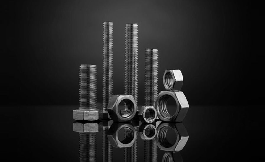
Stud bolts and nuts are the tensioning elements that compress flange gaskets and maintain joint integrity. A single incorrectly specified bolt can cause a flange leak with serious safety and environmental consequences.
Stud Bolt vs. Machine Bolt
| Type | Description | Application |
|---|---|---|
| Stud Bolt (Fully Threaded) | Threaded full length. Two nuts | Standard for ASME flanges. Preferred |
| Stud Bolt (Tap End) | One end shorter thread (tap end) into blind hole | Flanged valves, pump casings |
| Continuous Thread Stud | Fully threaded rod, cut to length | Standard for flanged joints |
| Hex Head Machine Bolt | Bolt with hexagonal head, one nut | Low pressure, non-critical. Less common in oil and gas |
Applicable Standards
| Standard | Scope |
|---|---|
| ASTM A193 | Alloy and stainless steel bolting for high temperature / high pressure |
| ASTM A194 | Carbon and alloy nuts for bolts |
| ASTM A320 | Alloy and stainless steel bolting for low temperature service |
| ASME B16.5 | Flange bolt dimensions and quantities |
| ASME B16.47 | Large-diameter flange bolting |
| ASME PCC-1 | Guidelines for pressure boundary bolted flange joint assembly |
| API 6A | Wellhead and Christmas tree bolting |
Common Bolting Specifications
| Bolt Grade (ASTM A193) | Nut Grade (ASTM A194) | Temperature Range | Service |
|---|---|---|---|
| B7 | 2H | -40°C to +400°C | Standard carbon steel. Sweet service. Most common in oil and gas |
| B7M | 2HM | -40°C to +400°C | Sour service. Controlled hardness (max HRC 22 / 235 HBW) |
| B16 | 4, 7 | Up to +500°C | High temperature. Cr-Mo-Va |
| B8 Class 1 | 8 | -196°C to +600°C | Stainless 304. General corrosion. Carbide solution treated |
| B8M Class 1 | 8M | -196°C to +600°C | Stainless 316. Chlorides, offshore |
| B8 Class 2 | 8 | -196°C to +600°C | Stainless 304. Strain-hardened. Higher strength |
| B8M Class 2 | 8M | -196°C to +600°C | Stainless 316. Strain-hardened. Higher strength |
| L7 | 4, 7 | -100°C to +400°C | Low temperature carbon steel |
| L7M | 7M | -100°C to +400°C | Low temperature + sour service |
| B7M | 2HM, 7M | -40°C to +400°C | Sour service standard |
NACE MR0175 / ISO 15156 Sour Service Requirements
- B7M / 2HM: Maximum hardness HRC 22 (235 HBW). Requires controlled chemistry and heat treatment
- B7 is NOT acceptable for sour service unless qualified to lower hardness
- Stainless bolting (B8M, etc.) must be carbide solution treated and meet hardness limits
Coating Options
| Coating | Description | Application |
|---|---|---|
| Black / Plain | As-manufactured, light oil | Indoor, non-corrosive |
| Hot-Dip Galvanized (HDG) | Zinc coating per ASTM A153 | Outdoor, atmospheric corrosion resistance |
| PTFE / Xylan | Fluoropolymer coating | Sour service, chemical resistance, prevents galling |
| Zinc-Nickel Electroplating | High-performance plating | Superior corrosion resistance, no hydrogen embrittlement |
| Xylan 1070 / 1424 | PTFE-rich coating | Standard for sour service bolting (low friction, anti-galling) |
| Cadmium Plating | Traditional anti-corrosion. Phased out (environmental) | Legacy. Not for new projects |
PIPING SPECIALTIES
Piping Specialties
Specialized Inline Equipment for Process Piping Systems
Beyond basic fittings, flanges, and valves, piping systems require specialty components for filtration, steam management, thermal expansion, and safety. Hoger Sanat Pars supplies these essential piping specialties with full compliance to applicable ASME, API, and project codes.
Product Categories
| Category | Function | Common Types |
|---|---|---|
| Strainers | Remove debris and particulates from flowing fluid to protect downstream equipment | Y-type, T-type/Basket, Cone, Duplex (duty/standby) |
| Steam Traps | Discharge condensate and non-condensable gases while retaining live steam | Thermodynamic, Float & Thermostatic, Inverted Bucket, Bimetallic |
| Expansion Joints | Absorb thermal expansion, vibration, and misalignment in piping | Rubber, Metal Bellows, Fabric, PTFE |
| Flame Arrestors | Prevent flame propagation in piping and tank vent systems | End-of-Line, In-Line, Detonation, Deflagration |
| Sight Glasses / Flow Indicators | Visual monitoring of fluid flow, color, or level | Double Window, Full View, Rotary |
| Blinds & Spacers | Positive isolation for maintenance | Spectacle Blind, Spade, Spacer / Ring |
Strainer Selection
| Type | Description | Application |
|---|---|---|
| Y-Strainer | Compact, Y-shaped body. Mesh or perforated screen | Pump suction protection, steam systems, small-bore |
| Basket Strainer (T-Type) | Large debris capacity. Accessible basket for cleaning | Large-bore, high flow, frequent cleaning |
| Duplex Strainer | Two strainer baskets with diverter valve. One active, one standby | Continuous operation, cannot shut down for cleaning |
| Cone Strainer (Temporary) | Low-cost conical screen for pipeline commissioning/startup | Temporary, removed after initial debris cleared |
| Tee Strainer | Strainer built into a modified tee fitting | Compact installation, instrument protection |
Mesh / Perforation Sizes: Typically 40 mesh (380 micron) to 200 mesh (74 micron) for process protection. Perforated screens for larger debris.
Materials: Carbon Steel (WCB), Stainless 316 (CF8M), Duplex, Hastelloy. Screens in matching or higher alloy.
Steam Trap Types
| Type | Operating Principle | Best For |
|---|---|---|
| Thermodynamic (TD) | Disc opens/closes based on dynamic pressure of flash steam | Drip legs, high pressure, outdoor, compact |
| Float & Thermostatic (F&T) | Float controls condensate level. Thermostatic vent for air/non-condensables | Process heat exchangers, jackets, kettles |
| Inverted Bucket | Submerged bucket floats/descends based on condensate level. Mechanical linkage opens valve | Robust, reliable, steam mains, high pressure |
| Bimetallic | Bimetallic strip expands/contracts with temperature to open/close valve | Low capacity, tracing, heating coils |
| Thermostatic (Bellows) | Liquid-filled bellows expands/contracts with temperature | Radiators, tracing, low pressure |
Expansion Joints
| Type | Description | Application |
|---|---|---|
| Rubber Expansion Joint | Elastomeric body with fabric reinforcement. Single or multiple arch | Water, slurry, low pressure, vibration isolation |
| Metal Bellows Expansion Joint | Stainless or Inconel bellows. Can include internal liner, external cover | High pressure, high temperature, steam, hydrocarbons |
| Fabric Expansion Joint | High-temperature fabric and insulation layers | Flue gas, exhaust, large-diameter ducting |
| PTFE Expansion Joint | Chemically inert, non-stick PTFE bellows | Strong acids, solvents, pure chemicals |
| Tied Expansion Joint | Tie rods limit axial movement. Takes lateral only | Where pressure thrust must be contained |
Flame Arrestor Types
| Type | Description | Application |
|---|---|---|
| End-of-Line Deflagration | Mounted at tank vent outlet. Stops atmospheric flame entry | Atmospheric storage tanks, vent lines |
| In-Line Deflagration | Installed in piping. Stops subsonic flame fronts | Process piping, vapour recovery |
| In-Line Detonation | Withstands supersonic shock wave from detonation | Long pipe runs, high-risk service |
| Endurance Burn | Resists continuous flame impingement for specified time | Flare gas recovery, tank blanketing |
Element: Wound crimped ribbon (aluminum, 316 SS, Hastelloy) creates narrow passages that quench flame by heat absorption.
Standards: ISO 16852, EN 12874, USCG