
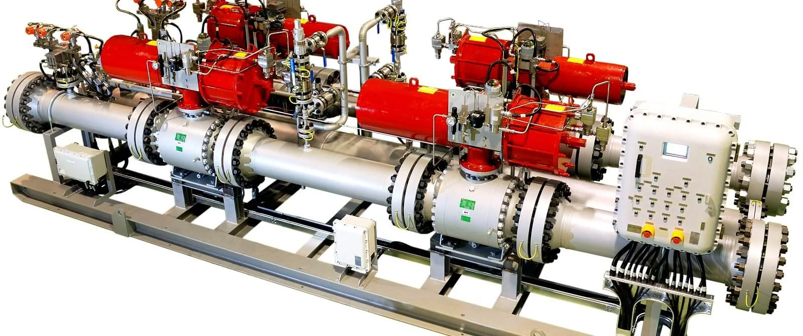
HIGH INTEGRITY PRESSURE PROTECTION SYSTEMS (HIPPS)
The Engineered Overpressure Safety Barrier — When Relief Is Not Enough
A High Integrity Pressure Protection System is not a valve. It is not a logic solver. It is not a sensor. It is a rigorously engineered, independently certified Safety Instrumented System (SIS) that prevents overpressure of downstream equipment by isolating the high-pressure source faster than a pressure relief valve can respond—and with a higher degree of safety integrity than conventional process shutdown systems can deliver.
HIPPS is specified when the consequence of overpressure is catastrophic, the relieving rate exceeds the practical capacity of relief valves and flare systems, or environmental and economic constraints make conventional relief technically unacceptable. In the hierarchy of overpressure protection, HIPPS sits above relief valves, above operator intervention, and above process alarms. It is the final, independent, auditable barrier.
Hoger SP supplies complete HIPPS packages—valves, actuators, logic solvers, sensors, and all ancillary components—from SIL 3 certified manufacturers with full traceability to IEC 61508 and IEC 61511. We do not assemble components. We deliver certified, tested, and documented safety loops ready for integration, Factory Acceptance Testing, and regulatory submission.
The Fundamental Problem HIPPS Solves
In a conventional process plant, overpressure protection is provided by pressure relief valves (PRVs) discharging to a flare or atmospheric vent system. This works when:
HIPPS
- The relieving rate is within the flare system’s hydraulic and thermal capacity
- The relief valve can open fast enough to prevent the pressure from exceeding code limits (typically 110% of MAWP for fire case, 116% for multiple valves)
- The flare system can handle the combined load of multiple simultaneous relief events
- Environmental regulations permit flaring of the relieved inventory
- The relief valve itself functions on demand—a mechanical device that may have been sitting unmoved for years
HIPPS is required when any of these assumptions breaks down:
| Scenario | Why Conventional Relief Fails | HIPPS Solution |
|---|---|---|
| High-pressure wellhead flowing into lower-rated gathering system | Full wellstream flow at shut-in pressure would overwhelm the gathering system flare capacity | HIPPS isolates the well before downstream pressure exceeds design limits |
| Gas injection compressor discharge into pipeline | Compressor discharge pressure exceeds pipeline design pressure. Full compressor throughput relief is impractical | HIPPS closes isolation valves within 2-5 seconds of overpressure detection |
| Pipeline incoming to processing plant | Pipeline inventory at high pressure. Flare cannot handle full pipeline blowdown | HIPPS isolates the plant inlet. Pipeline inventory remains contained upstream |
| Brownfield expansion | New production increases relieving load beyond existing flare capacity. Flare system upgrade cost is prohibitive | HIPPS provides overpressure protection without increasing flare load |
| Subsea tieback | Relief to atmosphere is impossible. Relief to subsea introduces hydrate and environmental risks | HIPPS isolates the high-pressure subsea source at or near the wellhead |
| Environmental constraints | Zero-flaring policy, carbon tax, or regulatory prohibition on routine flaring | HIPPS prevents the overpressure event entirely rather than managing its consequences |
HIPPS Architecture: The Building Blocks
A HIPPS is a complete Safety Instrumented Function (SIF) comprising three elements, all certified as a single loop to the target SIL level.
Element 1: Sensors (Initiators)
Pressure transmitters that continuously monitor the protected system. The HIPPS logic solver receives their signals and initiates a trip when the voting logic threshold is reached.
Typical Voting Architecture:
| Architecture | Sensors Required | Trips When | Safety Availability | Spurious Trip Risk | Application |
|---|---|---|---|---|---|
| 1oo1 | 1 | Sensor detects overpressure | Low | Low | SIL 1 only. Not recommended for HIPPS |
| 1oo2 | 2 | Either sensor detects overpressure | Medium | Higher (one sensor fail-high causes trip) | SIL 2. Less common |
| 2oo3 | 3 | Any two sensors detect overpressure | High | Low (one sensor fail-high does not trip) | SIL 3. Industry standard for HIPPS |
| 2oo4 | 4 | Any two sensors detect overpressure | Very High | Very Low | SIL 3 with enhanced availability. Critical service |
Sensor Requirements:
| Requirement | Specification |
|---|---|
| SIL Certification | SIL 3 per IEC 61508. Certified as a subsystem with documented failure data |
| Response Time | < 1 second from pressure change to signal output |
| Process Connection | Direct-mounted or remote diaphragm seal. Isolatable for testing and calibration |
| Communication | 4-20mA analog + HART digital. Direct-wired to HIPPS logic solver |
| Diagnostics | Continuous self-diagnostics. Internal fault detection with alarm |
| Redundancy | Three independent sensors. Separate process taps. Separate impulse lines. No common-cause failure points |
| Testing | Online proof testing capability without removing from service. Comparison checking between transmitters |
Element 2: Logic Solver
A dedicated safety PLC or solid-state logic solver that receives sensor signals, executes the voting logic, and commands the final elements to close. It is fundamentally separate from the process control system (DCS/PLC). The DCS controls the process under normal conditions. The HIPPS logic solver protects the process under abnormal conditions. They must not share hardware, software, or power supplies.
Logic Solver
Logic Solver Requirements:
| Requirement | Specification |
|---|---|
| SIL Certification | SIL 3 per IEC 61508. Certified by accredited body (TÜV Rheinland, TÜV Süd, exida, DNV) |
| Architecture | Fault-tolerant. 1oo2D (one out of two with diagnostics) or 2oo4D redundant architecture. No single point of failure |
| Independence | Physically separate from BPCS (Basic Process Control System). Separate power supply. Separate network. Separate marshalling |
| Response Time | Total loop response time (sensor detection + logic processing + final element closing) typically <2-5 seconds |
| Diagnostics | Continuous internal diagnostics covering CPU, memory, I/O modules, communication buses. Fault detection coverage >99% |
| Communication | Hardwired trip output to final elements. Optional digital communication (ProfiSafe, CIP Safety) for monitored valves |
| Bypass Management | Controlled, time-limited, password-protected bypass for sensor maintenance. Automatic alarm and logging. Cannot bypass all sensors simultaneously |
| Event Recording | Time-stamped Sequence of Events (SOE) recording for all trips, alarms, and operator actions. Typically 1ms resolution |
| Power Supply | Redundant. Dual independent power supplies with automatic switchover. Uninterruptible Power Supply (UPS) backup where required |
| Testing | Online testing of logic solver without interrupting protection. Automated diagnostic test routines |
Major HIPPS Logic Solver Manufacturers We Work With:
- HIMA Paul Hildebrandt GmbH: HIMax, HIQuad X, HIMatrix systems. The global reference standard for HIPPS logic solvers. TÜV SIL 3 certified
- Schneider Electric (Triconex): Trident and Tricon CX. Triple modular redundant (TMR) architecture
- Rockwell Automation (Allen-Bradley): AADvance and Trusted TMR systems
- Siemens: SIMATIC S7-400F/FH with Failsafe modules. S7-1500F for smaller configurations
- ABB: AC500-S and Safeguard 400 series
- Emerson (formerly GE / ICS Triplex): Trusted and AADvance platforms
Note: We do not represent any single logic solver manufacturer. We select and integrate the appropriate platform based on client specification, regional certification requirements, and existing site standardization.
Element 3: Final Elements
The final elements execute the HIPPS command: they close, isolate the high-pressure source, and hold against the full shut-in pressure. The final elements are typically two isolation valves in series (1oo2 architecture) to achieve the required SIL 3 integrity without requiring a single valve to be SIL 3 by itself.
Final Element Architecture:
| Architecture | Valves Required | Description | Application |
|---|---|---|---|
| 1oo1 | 1 | Single HIPPS isolation valve | SIL 2 only. Not recommended for SIL 3 HIPPS |
| 1oo2 | 2 in series | Both valves close on trip. Either valve alone stops flow. If one fails to close, the second provides protection | SIL 3. The industry standard for HIPPS final elements |
| 2oo2 | 2 in parallel | Both valves must close to stop flow. Higher availability (less spurious trips) but lower safety integrity | Rare. When spurious trip cost is extreme |
| 2oo3 | 3 | Two out of three valves must close | Very high availability + high safety integrity. For critical subsea or offshore HIPPS |
HIPPS Isolation Valve Requirements:
| Requirement | Specification |
|---|---|
| Valve Type | Through-conduit slab gate valve (API 6D or API 6A) or trunnion-mounted ball valve (API 6D). Full bore. Piggable |
| Shutoff Class | API 598 Zero Leakage or FCI 70-2 Class VI (bubble-tight). Metal-to-metal seal with soft secondary or fully metal-seated with certified low leakage |
| Fire-Safe | API 607 or API 6FA certified. Must maintain shutoff during and after fire exposure |
| SIL Certification | Certified as final element subsystem per IEC 61508. Typically SIL 2 individually. SIL 3 achieved with 1oo2 architecture |
| Stroking Speed | Full stroke (open to close) typically 2-5 seconds. Faster for high-velocity gas pipelines. Must not cause water hammer |
| Actuator | Pneumatic (spring-return fail-close) or hydraulic (accumulator-return fail-close). Double-acting with stored energy accumulator also used |
| Stored Energy | For actuators requiring power to close: dedicated gas accumulator bottle or hydraulic accumulator. Sufficient for full stroke + safety margin |
| Solenoid Valves | Redundant. 1oo2 or 2oo2 voting. Low solenoid energized to trip (de-energize to trip). Certified SIL 3 as a component |
| Partial Stroke Testing | Automated PST system. Moves valve 10-20% of stroke at scheduled interval without interrupting process. Verifies valve is not stuck. Extends full proof test interval |
| Position Feedback | Dual redundant position transmitters (4-20mA). Confirms valve fully open or fully closed. Used for diagnostics and PST verification |
| Sour Service | NACE MR0175 / ISO 15156 compliant materials. Controlled hardness (≤22 HRC for carbon steel components). HIC/SSC tested |
| Material | Body per ASME B16.34. Trim in 316 SS, Duplex, or Inconel 718 depending on service. Hardfaced seat and gate/ball as required |
HIPPS Loop Design & SIF Verification
A HIPPS is not a catalogue product. It is an engineered safety loop. The design process is iterative and documented:
HIPPS Loop Design
Step 1: Overpressure Scenario Identification
Define the credible overpressure scenarios. Typically:
- Upstream well at shut-in tubing pressure (SITP) flowing into lower-rated downstream piping
- Gas injection compressor at maximum discharge pressure
- Upstream pipeline at maximum operating pressure (MOP) flowing into lower-rated plant inlet
Step 2: Required Safety Integrity Level (SIL) Determination
Conduct a Safety Integrity Level (SIL) assessment per IEC 61511 using:
- Layer of Protection Analysis (LOPA): Quantify the gap between the unmitigated risk frequency and the tolerable risk frequency
- Risk Graph: Qualitative or semi-qualitative method per IEC 61511 Annex D
The LOPA determines the Probability of Failure on Demand (PFDavg) required from the HIPPS. Typically SIL 3 is required (PFDavg < 1×10⁻³ to 1×10⁻⁴).
Step 3: Loop Architecture Selection
Select sensor voting (typically 2oo3), logic solver redundancy (typically 1oo2D), and final element architecture (typically 1oo2) to achieve the target PFDavg.
Step 4: SIF Verification Calculation
Calculate the PFDavg of the complete HIPPS loop:
Where:
- Each subsystem PFDavg is calculated from the certified failure rate data (λDU) and the proof test interval (TI)
- PFDavg(subsystem) ≈ λDU × TI / 2 (for a simple 1oo1 subsystem)
- PFDavg(2oo3 sensors) is a more complex calculation accounting for common cause failures
- PFDavg(1oo2 final elements) accounts for common cause failure factor (β-factor, typically 5-10%)
Step 5: Proof Test Interval Determination
The proof test interval must be practical for operations. If the calculated TI is too short (e.g., 6 months on a continuously operating plant), consider:
- Partial Stroke Testing to extend the full proof test interval
- Higher-reliability components (lower λDU)
- More redundant architecture
Step 6: Documentation
The complete HIPPS safety requirements specification, SIF design, verification calculations, and test procedures are compiled into the HIPPS Safety Manual and submitted for regulatory review where required.
HIPPS Testing & Ongoing Validation
HIPPS is not a “fit and forget” system. It requires periodic testing throughout its operational life to maintain the SIL certification.
| Test Type | What It Does | Frequency |
|---|---|---|
| Full Proof Test | Full-stroke closure of each HIPPS valve from fully open to fully closed. Verification of sensor trip points. Logic solver function test | Typically every 1, 3, or 5 years per SIF verification. During plant turnaround |
| Partial Stroke Testing (PST) | Moves valve 10-20% of stroke without interrupting flow. Verifies valve is not stuck. Detects dangerous undetected failures | Typically monthly or quarterly. Automated. Extends full proof test interval |
| Sensor Comparison | Compares readings of the three redundant pressure transmitters. Alarms if one deviates from the median by more than a configured tolerance | Continuous. Automated in logic solver |
| Logic Solver Diagnostics | Internal self-test of CPU, memory, I/O, communication. Fault detection coverage >99% | Continuous. Automatic fault alarm |
HIPPS Documentation Deliverables
Every HIPPS we supply is accompanied by:
| Document | Content |
|---|---|
| HIPPS Safety Requirements Specification (SRS) | Functional description, SIL target, trip setpoints, response time, voting logic |
| SIL Certificate (Logic Solver) | Manufacturer SIL certificate from TÜV/exida/DNV stating SIL 3 capability |
| SIL Certificate (Final Elements) | Valve + actuator + solenoid certificate. SIL 2 or SIL 3 as an assembly |
| FMEDA Reports | Failure Modes, Effects, and Diagnostic Analysis for each subsystem. Provides λS, λD, λDU, λDD |
| SIF Verification Calculation | Detailed PFDavg calculation for the complete HIPPS loop. Demonstrates compliance with SIL target |
| HIPPS Safety Manual | Installation, operation, maintenance, proof test, and PST procedures. Bypass management |
| FAT Procedure & Report | Factory Acceptance Test. Simulated overpressure trip. Verification of response time, voting logic, valve closure |
| Material Certificates (MTRs) | EN 10204 Type 3.1 or 3.2 for all pressure-containing and safety-critical components |
| Valve Test Records | Shell hydrostatic test. Seat leakage test (API 598 Zero Leakage or FCI 70-2). Functional test with actuator |
Global Regulatory Framework
| Standard | Scope |
|---|---|
| IEC 61508 | Functional safety of electrical/electronic/programmable electronic safety-related systems. The parent standard |
| IEC 61511 | Functional safety for the process industry sector. Application of IEC 61508 to process plants |
| API RP 14C | Recommended practice for analysis, design, installation, and testing of safety systems for offshore production facilities |
| API RP 521 | Guide for pressure-relieving and depressuring systems. Addresses HIPPS as an alternative to relief |
| ASME Section VIII Div 1 / Div 2 | Pressure vessel code. Recognizes HIPPS as an overpressure protection method in certain jurisdictions |
| PED (Pressure Equipment Directive) | European directive. Acceptance of HIPPS as overpressure protection subject to notified body approval |
| NORSOK P-100 | Norwegian standard for process systems. HIPPS accepted |
| ISO 10418 | Offshore production installations — analysis, design, installation and testing of basic surface process safety systems |
HIPPS vs. Relief Valves: The Total Cost of Ownership
| Cost Element | HIPPS | Relief Valve + Flare |
|---|---|---|
| Capital (Equipment) | HIPPS valves, actuators, logic solver, sensors, PST system | Relief valves, flare header, flare tip, knockout drum, flare stack |
| Capital (Structure) | Minimal. Valves in-line with piping | Flare stack structure, guy wires, foundation, heat radiation fencing |
| Capital (Land) | Zero additional land | Significant land for flare radiation exclusion zone |
| Operating | Minimal. Periodic proof testing. PST automated | Flare purge gas continuous consumption. Flare tip maintenance |
| Environmental | Zero emissions during event | Flaring. CO₂, NOx, SOx, unburned hydrocarbons |
| Regulatory | Requires SIL submission and regulatory approval | Established technology. Widely accepted by regulators |
| Public Perception | Invisible to public | Visible flame. Noise. Smoke. Community complaints |
How We Deliver HIPPS
We are not a HIPPS manufacturer. We are a procurement and integration partner who delivers complete, certified HIPPS packages by:
Deliver HIPPS
- Manufacturer Selection: We match your project requirements (SIL target, regional certification, client preference, existing site systems) to the appropriate logic solver and final element manufacturers
- Single-Source Supply: Valves, actuators, logic solver, sensors, solenoids, PST system, and all ancillary components sourced and delivered as one package
- FAT Coordination: We witness and document Factory Acceptance Testing at the manufacturer’s facility before shipment
- Documentation Compilation: The complete HIPPS dossier—SIL certificates, FMEDA reports, SIF verification calculation, safety manual, FAT record, material certs—delivered as an auditable package
- Aftermarket Support: Spare parts, proof testing support, PST system maintenance, actuator seal kits, solenoid replacements
Contact Our Safety Systems Team
HIPPS specification requires detailed process data and safety analysis. Our technical team can support your project from SIL determination through to final documentation. Contact us with your overpressure scenario, and we will work with our manufacturing partners to propose a certified solution.